Our pumps are primarily designed to efficiently supply potable water to off-grid remote site dwellings and for other low volume intermittent duty applications.
It consists of the following components:
1. (1) 85 Watt solar
module.
2. (1) 12 volt Submersible Solar Water Pump, or 24 volt model - please specify.
3. (1) Model PPT 12-24-7V Linear Current Booster not for use with battery.
|
|
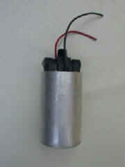
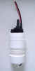
Water Pump
Click
to enlarge
|
Solar Module
 |
Solar
Controller for no battery system

Click
to enlarge
|
|
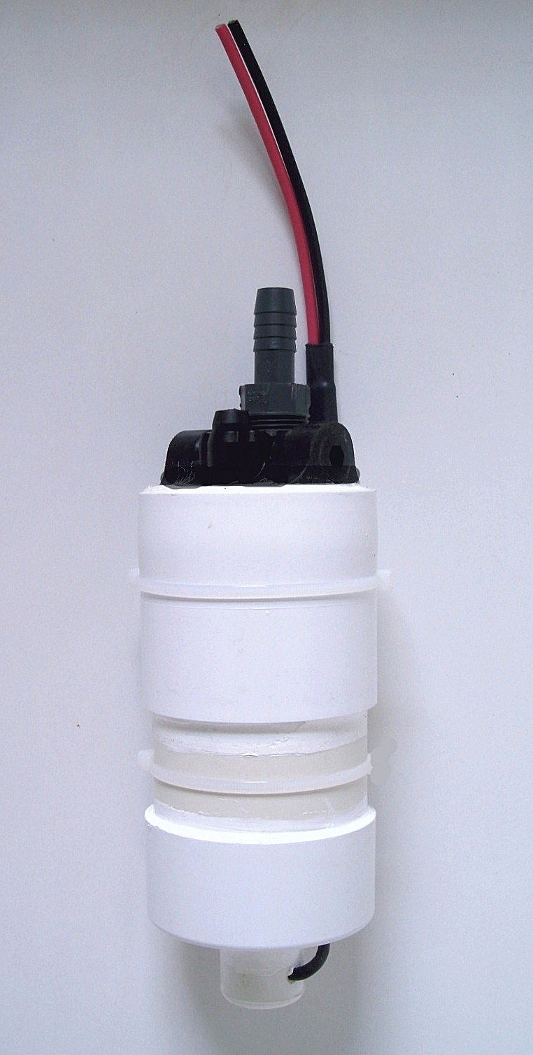
The New Version 2 Submersible DC Well Pump is a complete ready-to-install DC powered submersible well pump. It features a super-watertight corrosion and rust proof PVC case specifically designed for and fitted to a Flojet motor and Flojet duplex diaphragm pump head.
This combination results in a high quality, energy efficient, and exceptionally cost-effective submersible well pump unit with a wide range of applications.
SPECIFICATIONS
CASE: The V2 corrosion and rustproof PVC case fits 4" or larger wells.
MAIN CASE SEAL: Hydraulic compression fit PVC junction reinforced with marine adhesive sealant.
WIRE LEADS: 18" color-coded 10 AWG vinyl insulated stranded copper with outer PVC cable cover.
Each pump includes a set of sealant filled crimp connectors and heat shrink tubes for connecting pump leads to drop wire.
WIRE LEAD SEALS: Integrally installed in embedded waterproof sealant filled plug.
INTAKE FILTER: Inlet port with 20 mesh stainless steel filter.
DISCHARGE FITTING: 3/4" Threaded X 1/2" Barbed Adapter fits 1/2" flexible pipe or tube.
FLOJET pumps feature industrial grade head/motor units with the following specifications:
MOTOR: Low current draw permanent magnet, ball bearing drive, 2,000 hour brush life.
PUMP HEAD: Positive displacement, duplex diaphragm design tolerates passage of small foreign particles and can be run dry without damage.
PERFORMANCE: Typically 1 to 2 GPM depending on lift height (head) and operating voltage. Maximum head is rated at 230 feet. All models, the 12 Volt DC, the 24 Volt DC, and the 115 Volt AC/DC, have the same performance characteristics and GPM delivery rates.
POWER DRAW: Typically 50 watts - 100 watts depending on depth of lift.
|
This is a Lift/Amps/Flow Chart for the Flojet pump model used in the 24 Volt Submersible Pumps. For 12 Volt Pumps, the lift and GPM Flow is the same but the amperage rating is double.
| LIFT IN FEET |
AMPS |
GPM |
| 23 |
2.06 |
1.83 |
| 46 |
2.54 |
1.77 |
| 69 |
2.90 |
1.65 |
| 93 |
3.12 |
1.57 |
| 116 |
3.35 |
1.47 |
| 139 |
3.58 |
1.38 |
| 162 |
3.79 |
1.32 |
| 185 |
4.00 |
1.26 |
| 208 |
4.20 |
1.20 |
| 231 |
4.40 |
1.15 |
GENERAL GUIDE TO INSTALLATION & OPERATION
PREFACE: This document is intended as a general guide to understanding the installation and operation of the Submersible/Flojet Pump Unit. It does not contain complete information regarding safe and proper plumbing and electrical practice as well as information regarding the differing conditions of specific installations. If in doubt, proceed with caution and/or seek professional assistance.
SYSTEMS - Typically, a storage tank, a pressure tank, or a combination of both (storage tank to booster pump to pressure tank) is part of a submersible pump water system.
OTHER FACTORS include power source voltage and regulation, distance between power source and pump, and height between pumps and tank (head).
Available power source voltage determines pump voltage.
Distance between pump and power will determine gauge of electrical wire relative to pump amperage. (See Chart.)
For longevity of small submersibles, use either a storage tank or combination system.
EXAMPLE:
Well depth..............................................60'
Distance pump to power..........................65'
Static water level..................30' below grade
Level of pump.......................40' below grade
Pump amps-volts.....................3.5 @ 24VDC
Wire size.......................................12 gauge
Height pump to tank.................................55'
Tank type................storage w/float switch
INSTALLATION PROCEDURE:
1. Thoroughly read all literature included with the Pump.
2. Lie out delivery pipe, electrical wires, and pump near wellhead.
3. Connect one end of pipe to pump (use s.s. hose clamp).
4. Install appropriate fitting at other end of pipe.
5. Solder electrical wires to pump leads, or connect wires with
non-insulated crimp connectors or other crimp connect device. Embed connection in marine sealant (3M 4200 or 5200 Fastcure or equiv.) and cover w/heat shrink tubes or other standard submersible pump wire splice seal device. Allow ample time for sealant to set prior to immersion.
WARNING: Take Care! If this connection leaks your pump will fail.
6. Bundle pipe and wire at 5' +/- intervals with cable ties and be sure that spliced wires at pump do not protrude beyond diameter of case.
7. Lower pump into well to a point below static water level (1' to Maximum 20'). Note: A safety line is not required.
8. Connect pipe from tank to pipe from well.
9. Connect electric wires from tank switch to wires from pump. (Protect circuit w/10 - 12-amp fuse.)
10.Review all procedures in thorough detail to determine if entire system and all plumbing and electrical connections have been installed and secured in complete accordance with professional standards.
CAUTION: Only proceed with plumbing and/or electrical connections if qualified. Otherwise, seek advise of professional plumber/electrician.
WARNING: Major damage to pump motor can result if pump is operated when water in delivery pipe is frozen or otherwise obstructed; the pumps are not equipped with bypass valves.
OPERATION - To prevent pump damage or excessive wear, Pressure Tank Systems must be fitted with a pressure switch that switches pump off before total system pressure exceeds maximum rated pump pressure. Total system pressure is equal to the poss. of head (each 2.31of head = 1 poss.) plus poss. Of pressure switch shut-off setting. Total system pressure should not exceed maximum rated pump pressure (up to 100 poss. for standard Flojet pumps).
To prevent overflow and excessive pump wear, a Storage Tank System (best system for small subs) must be fitted with a float or water level sensor switch. Being that a storage tank is not under pressure, total system pressure is simply equal to poss.
Pumps operated direct from photovoltaic modules should be protected from excessively high voltage inputs via a manual or automatic disconnect switch at power source, and/or, an appropriately sized and compatible linear current booster (LCB) device.
For proper operation of pump, electrical circuit must be suitably fused, grounded, and equipped with main disconnect switch at power source.
APPROPRIATE USE: Our Pumps are primarily designed to efficiently supply potable water to off-grid remote site dwellings and for other low volume intermittent duty applications. Expected years of maintenance free service will be proportionately shortened if high volume continuous duty applications exceed the designed use.
TROUBLE PREVENTION NOTE - Most pump failures are caused by improper installation and/or operation. Extra careful attention should be given to electrical wire connection and waterproofing, submergence depth, total system pressure, motor overload conditions, and under or over voltage inputs.
(NOTE-The text above is the formal version of the installation procedure, with all the superfluous cautions, warnings, details, etc. In actual practice, the procedure is much simpler than this inflated document suggests. But please do read it; there are a few important points included that could spell failure if ignored.)
IMPORTANT! We need to know the depth of your well, and the depth to the water. No estimates please. It is important to the proper installation and operation of the pump. There is a 230-foot limit and a maximum operating pressure of 100 PSI only allowed.
| Our 30 DAY LIMITED WARRANTY:
If the Flojet pump fails within the warranty period due to a defect in the materials and/or workmanship of our Case, we will promptly replace the complete Submersible Pump unit after examining the unit. The Customer is responsible for all shipping and handling
charges. We do not warranty Flojet brand pumps. (Flojet Corporation 1-800-2FLOJET warrants Flojet pumps, but they may not warranty pump motors that have failed due to direct contact with water). We also do not warranty the workmanship of whoever installs your pump into your water source. Any replacement of a our Submersible Pump unit is conditional upon (1) a complete description of the installation and the postpaid return of the complete original unit with attached wire connection devices included, (2) our examination of the returned unit, (3) our determination that failure was a result of our materials and/or workmanship being defective and not due to a defective Flojet pump, a defective installation of the pump into your water source, or any application of the pump which exceeded the use for which it was designed (see Our User Guide), and (4) a return authorization by email or telephone prior to the return. Note: Any questions or concerns regarding our Submersible Pump, either under warranty or after warranty expiration, can be conveyed to
chinadepot@aol.com for consultation. |
|


)